Interactive model with speed and direction controls
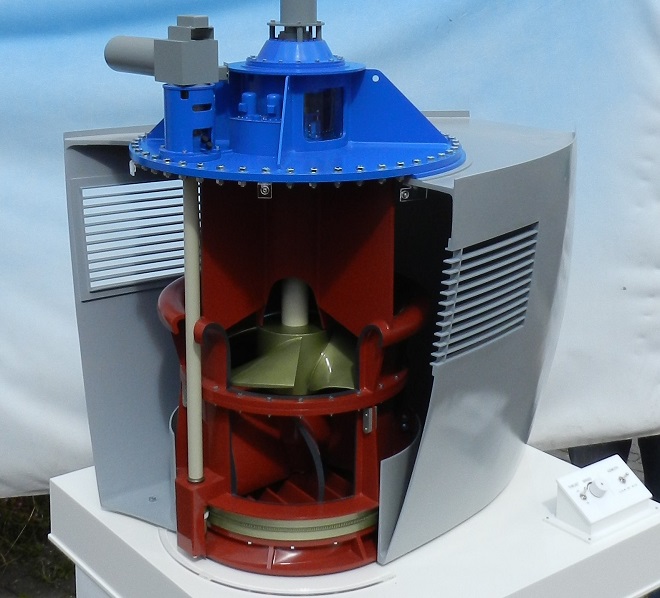
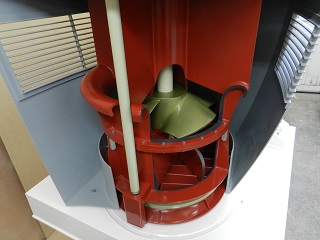
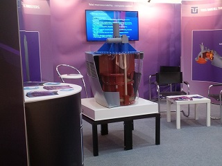
This unusual industrial model was a real challenge on two fronts – firstly because of the very complex shaped components involved but also because of the requirement for a very specific interactive element. The thruster comprises a large propeller that forces water downwards through a deflector that can be rotated through 360 degrees to direct the water thrust in any direction. This is the USP of the client’s product and, as such, he wanted the model to incorporate a rotating propeller (with speed control) and a movable deflector (clockwise and anti-clockwise) at 6rpm. We also had to work out how to mount the model in a cut-away view of a ship’s bows and create a cut-away view of the thruster to show the main working components. The model was recently shipped in a large flight case to a trade event in Germany – one of the inset images shows it on their stand.
Revolving Globe Display
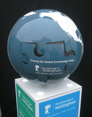
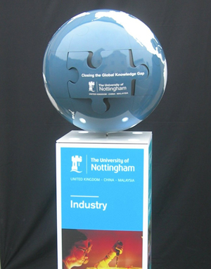
The client for this project, Nottingham University wanted to create an eye catching icon that they could use as a marketing tool at various promotional events. To emphasize their strong overseas connections they wanted to visually portray their marketing strap line “Closing the Global Knowledge Gap” by creating a world globe made up from jigsaw shaped pieces with their logo as the final piece of the puzzle. We developed this brief from loose concept stage to a fully realized functional display that they could transport and set up easily themselves at any venue. We even threw in the idea of making the globe rotate slowly and up-lighting it from below to add extra visual impact. The globe itself was made from fiberglass (for strength and lightness) with a painted and lacquered finish.
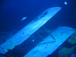
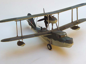
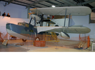
Replica of Vintage Aircraft
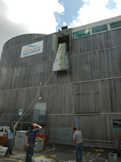
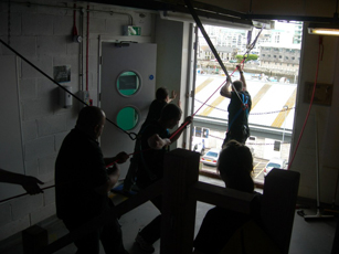
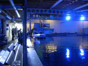
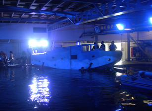
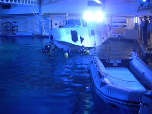
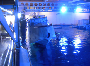
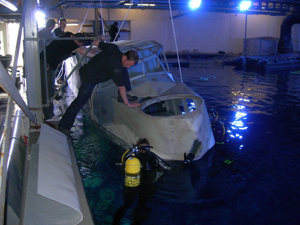
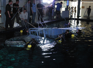
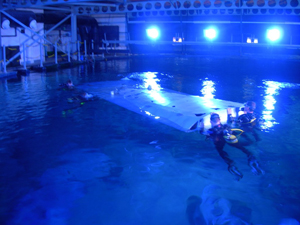
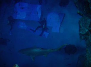
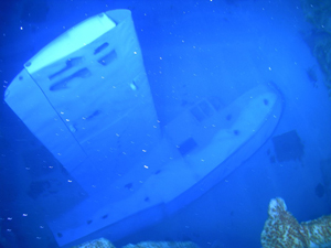
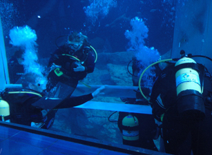
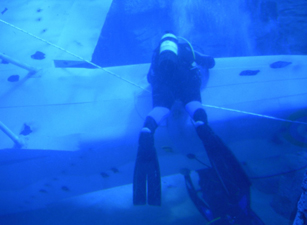
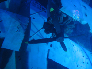
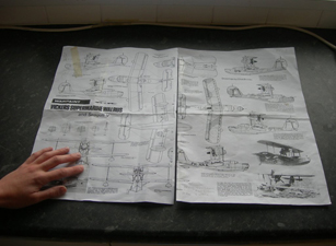
This is actually the final stage of a project we started in March . It’s a fibreglass replica of a crashed World War 2 seaplane, a “Vickers Supermarine Walrus” and what’s especially unusual about this model is that it is actually underwater. When the National Marine Aquarium at Plymouth decided they wanted an unusual display to put in their huge sea water tank, they avoided the obvious route of a sunken ship and went instead for this wrecked seaplane. They chose the Walrus because it had strong historical links with the area. If you visit the aquarium’s web site you can read the full story (link below). At 12 metres long and with a 14 metre wing span it was one of the biggest projects we had ever undertaken and one of the most technically demanding. Our starting point was a small set of paper plans, a photograph of a model, and some photos of the real thing at the Royal Fleet Air Arm Museum. When working out how to make it, the design process was complicated by several factors. It had to be transportable from Cardiff to Plymouth. It had to go into the aquarium through a small door three stories up the building. It had to be reassembled in a small space on top of the 9 metre deep tank. It had to sink (obviously). Divers had to be able to do the final assembly under water. And it had to be structurally sound and be able to withstand being under water for many years. Furthermore we had to design the damaged areas in a way that wouldn’t injure or trap the fish. It was a difficult project to photograph due to restricted viewing lines into the tank, but hopefully the images we’ve shown give a good indication of how the finished display looked. If you scroll down through the images below you can also get a flavour of the installation process. It was certainly a challenging but enjoyable day for us and the aquarium’s team of divers. The sharks and other fish seemed to find it pretty entertaining too.
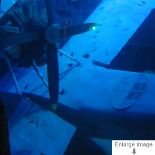
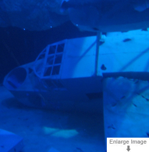
Image Gallery
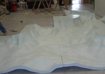
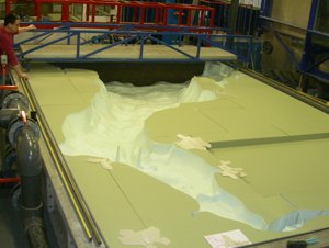
River Bed Model in Fibreglass – Horizontal Scale 1:125,000, Vertical Scale 1:125
Commissioned by Cardiff University’s Engineering Department, this 6 metre x 4 metre fibreglass model of the River Severn Estuary and Bristol Channel river beds was a very technically demanding job, not just because of the huge volume of complex data involved but also because of the sheer size of the project. Comprising several large sections that bolted together, it had to be an accurate representation of the riverbed contours (at an exaggerated vertical scale) because it was being used for physical experimentation in a major research program on tidal power generation.
How we made it
The first stage was to create a “mirrored” negative (upside down and back to front) version of the river bed contours all the way from Gloucester, down the Bristol Channel as far as the open sea. This comprised six major sections and several smaller, infill sections. These contours were made from laser cut acrylic layers supported on an MDF substructure, all fixed onto a structural base board with upstanding sidewalls. To construct the accurate depths and contours we had to create our own CAD masterplan using a combination of traditional Admiralty Charts, CAD contour maps, reams of numbers giving spot depths, and numerous sections through the river bed at key areas.
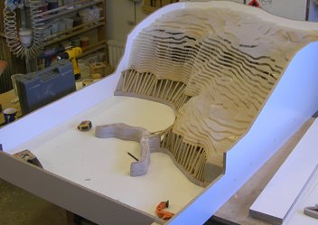
Once the basic structures of the moulds were built, the contours then had to be blended into a smooth continuous “land-form” using various filling techniques. At the same time great care had to be taken to ensure the contours matched perfectly across the joins between the sections. The contours then had to be sealed and “polished” to a fine finish so that the fiberglass forms would come away cleanly from the moulds once they had cured.
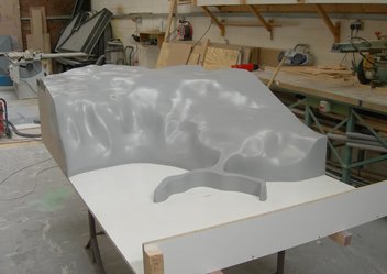
The final stage was to layer up resin and fiberglass matting into the moulds, starting with the “gelcoat” layer (which is in effect the top layer and is the visible finished colour) and then several more layers of resin and matting to build up the structural integrity. The fibreglass sections were then eased out of the moulds and flipped the right way up, ready to be joined together on to a structural sub-frame which supported them all at the right height. The image shows the sections just after they have come out of the moulds. They had been loosely assembled on the floor to check for fit.